Advanced SIMPLIS Training
Advanced SIMPLIS Training
|
In this Topic Hide
How models can be configured with different levels of complexity with a single parameter.
The model level used can then be selected based on your simulation objective.
Open the schematic titled 1.1_SelfOscillatingConverter_POP_AC_Tran.sxsch.
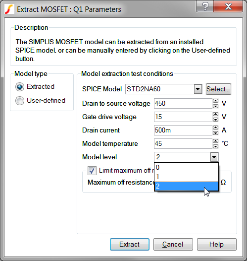
Double click on the MOSFET Q1.
Result: The Extract MOSFET Dialog opens.
Click
on the Help Button in the lower right corner of the
dialog.
Result: The Help system opens to the SIMPLIS
MOSFET Models topic.
At this point, you should have both the Extract MOSFET Dialog and the SIMPLIS MOSFET Models help topic open.
MOSFETs, in common with the other semiconductors such as Diodes, Zener Diodes, IGBTs and JFETs have very nonlinear behavior. For example, the drain-to-source capacitance of a MOSFET can radically change as the voltage across the MOSFET changes from the blocking to the conducting state. If you are interested in the switching behavior of this device, it is important to model this capacitance change; However, if you primarily interested in the Bode Plot of the converter, the details of the switching transition are typically not important.
SIMPLIS has the ability to change both the underlying schematic structure and the parameters of a model based on a single parameter value. In the Extract MOSFET Dialog, and indeed, in many SIMPLIS built-in models, the "Level" or "Model Level" parameter controls the schematic view of the model which is used in the simulation.
The MOSFETs used in SIMPLIS have four levels of complexity. Each level is described in detail in the currently open help topic. Below are the schematic views of the level 0 , 1, and 2 models. The level 3 model is intended for user-customized models, and is not supported by the internal model extraction routines.
| Level 0 Model | Level 1 Model | Level 2 Model | ||||||||||||||||||||||||||||||||||||
|
|
|
||||||||||||||||||||||||||||||||||||
|
|
|
The Level 0 MOSFET is used whenever the detailed switching action of the MOSFET is not important. The Level 2 MOSFET, which models the nonlinear capacitances, is typically used when the switching transitions are important, such as when measuring efficiency. The Level 1 MOSFET is used for power stage development when the converter topology relies on the MOSFET output capacitance.
If you have closed the Extract MOSFET dialog, reopen it by double clicking on the MOSFET Q1.
Click Extract.
Result: A progress bar briefly displays
the progress as SIMetrix/SIMPLIS extracts the SIMPLIS model parameters
from the SPICE model.
Look in the SIMetrix/SIMPLIS command shell window. (Hint: You
can press the space bar to bring the command shell into view.)
You should see the following message:
Extracting SIMPLIS
model for STD2NA60. Please wait..
Complete
You have just executed several SIMetrix SPICE simulations on the SPICE model for the STD2N60 MOSFET, curve-fit the SPICE simulation data to a SIMPLIS PWL model, and written 66 model parameters to the symbol. Congratulations! Nice work!
The Multi-Level Modeling concept is at the core of this process - that models can have varied complexity based on the application. You can maximize simulation speed by using the minimum model level required for your analysis.
As you have just seen, SIMetrix/SIMPLIS has the unusual ability to simulate Spice semiconductor models and from these results to extract a PWL SIMPLIS model. This capability becomes especially powerful when you combine it with the Multi-Level Modeling concept. Now critical device models can have the appropriate level of complexity based on the simulation objective of a particular simulation run. You can maximize the speed of each simulation by using the lowest level of complexity required to achieve the desired accuracy.
Double click on the output capacitor C1.
This is the first electrolytic capacitor symbol to the right of the
transformer output.
Result: The Edit Device Parameters dialog
for the electrolytic capacitor opens:
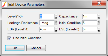
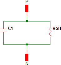
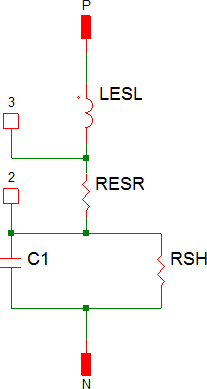
SIMetrix/SIMPLIS has two electrolytic capacitor models; the first has model levels 1-3, and a second, more detailed model, has levels 4 and 5. The three electrolytic capacitors on this schematic all use the Level 1-3 model and have the model level set to 2. Equivalent schematic images of the Level 1-3 models are shown below:
Level 1 |
Level 2 | Level 3 | ||||||||||||||||||
|
|
|
||||||||||||||||||
|
|
|
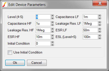
The Level 4-5 model for the electrolytic capacitor models the low and high frequency components separately. The model is essentially two electrolytic capacitors in parallel. The edit dialog for the Level 4-5 electrolytic capacitor is shown below:
The schematic views of the level 4 and level 5 models are shown below. The Level 5 model adds a Equivalent Series Inductance (ESL) to the Level 4 model.
| Level 4 | Level 5 | ||||||||||||||||||||||||||
|
|
||||||||||||||||||||||||||
|
|
For future reference, you can place the Electrolytic Capacitors from the SIMPLIS parts selector:
|
© 2015 simplistechnologies.com | All Rights Reserved