DVM - Design Verification Module
DVM - Design Verification Module
|
The Basic DVM Control symbol holds the minimum amount of information that is required to run DVM. Before you add a DVM
To add a basic DVM symbol to a working schematic, follow these steps:
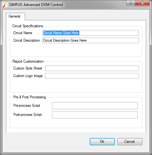
Double click the symbol.
Result: The dialog shown below opens for
you to change the general information, which is described in the table
below.
| Label | Parameter Description |
| Circuit Specifications: General information about the circuit | |
| Circuit Name | Name of the circuit as it will appear in the DVM report; for display purposes only. |
| Circuit Description | Description of the circuit under test which appears in the DVM Control symbol; for display purposes only. |
| Report Customization: Options to customize the appearance of the DVM report | |
| Custom Style Sheet | Cascading Style Sheet (CSS) file to use with the DVM report |
| Custom Logo Image | Portable Network Graphics (PNG) file to use with the DVM report |
| Pre & Post Processing: Options to control the default pre- and post-processing options for circuit | |
| Pre-process Script | SIMetrix script to be executed immediately before launching each simulation; this allows you to adjust a schematic before running the test. |
| Post-process Script | SIMetrix script to be executed immediately after each simulation successfully completes; this allows you full access to perform waveform manipulation and create custom scalar and spec values. |
© 2015 simplistechnologies.com | All Rights Reserved