This topic gives an overview of how the periodic operating point analysis finds the periodic switching steady-state operating point of a circuit.
To download the examples for Module 2, click Module_2_Examples.zip
In this topic:
Key Concepts
This topic addresses the following key concepts:
- POP only works on switching circuits.
- A triggering gate is required by the POP analysis.
- The Core POP Process recursively refines its estimate of the set of initial conditions for the circuit that are consistent with steady-state operation.
- The user-defined initial conditions have a dramatic effect on the speed with which the POP Analysis is able to find the steady-state Periodic Operating Point of a system.
What You Will Learn
In this topic, you will learn the following:
- An overview of the Periodic Operating Point (POP) analysis.
- Which POP parameters are used in each of the four phases of the Periodic Operating Point analysis.
- That POP must have a triggering gate defined.
- The schematic POP Trigger Device is an easy way to define the POP trigger gate.
Getting Started
Exercise #1: Running a SIMPLIS POP Analysis
- Open the schematic 2.7_SelfOscillatingConverter_POP.sxsch.
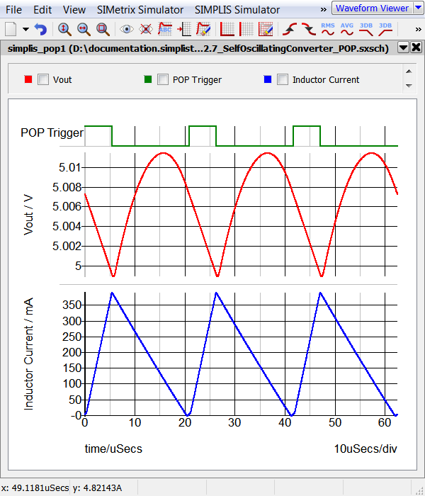
- Run the simulation. Result: The POP analysis runs and 3 cycles of the POP Trigger, Output Voltage and Inductor Current are output to the waveform viewer.
Discussion
The periodic operating point (POP) analysis you just ran is unlike any other analysis. POP is actually a sequence of transient simulations, run back to back, where the initial conditions are adjusted and refined between each run. From a high level view, POP can be broken into four major phases, labeled A-D in the flow chart image below:

|
In the first phase of the POP process, a regular SIMPLIS transient simulation is initiated using the user-specified initial conditions. |
| During this phase, SIMPLIS performs a transient simulation for a fixed number of switching cycles. Once the user-specified number of "Cycles before launching POP analysis" have been simulated, the Core POP Process is launched. | |
| The Core POP Process executes a series of transient simulations, recursively adjusting the initial conditions of the circuit before each subsequent pass or iteration of POP algorithm. A successful POP analysis concludes when SIMPLIS finds the steady-state Periodic Operating Point of the circuit. | |
| After the Core POP Process finds the steady-state Periodic Operating Point of the circuit, a transient analysis is executed for a user-specified number of cycles. At the beginning of this transient analysis, the time variable is reset to zero. |
Even with this high level view of POP, a few points are already clear:
- The entire POP process is based on the assumption that the circuit exhibits a periodic switching behavior. Therefore, if the circuit ever ceases to switch, the POP analysis will fail.
- The result of the POP analysis is a set of initial conditions that put the circuit immediately into steady-state operation. By using these initial conditions for subsequent transient and AC analyses, the user can save a great deal of time since they no longer have to wait for long time constants to settle as is the case when using a conventional long transient simulation to reach steady state.
- The closer the user-defined initial conditions are to the steady state of the system, the faster the Core POP Process will be able to converge to the eventual steady-state solution.
Configuring the POP Dialog
The parameters which control a POP analysis are entered on the Choose Analysis... dialog. The dialog for the 2.7_SelfOscillatingConverter_POP.sxsch design is shown below, with the controls used for each phase of the POP analysis labeled A, B, C and D.

- The parameters set in the Triggering section are applied to all phases of
the POP process. Checking the box "Use POP Trigger schematic device" tells SIMPLIS
to look for the schematic POP trigger device in the design hierarchy, and if
present, use that signal as the periodic indicator of the beginning of each new
switching cycle. If the POP Trigger schematic device is not found in the schematic
hierarchy, an error message is generated:

- The Maximum period parameter sets the maximum expected switching period for the POP analysis. If the converter oscillates at a longer period than the specified parameter, an error will occur. This error message will be output to the SIMetrix/SIMPLIS command shell.
- The Cycles before launching POP is the number of time-domain transient switching cycles which SIMPLIS simulates before starting the Core POP process.
In the next section, the Core POP Process is discussed in detail.
Conclusions and Key Points to Remember
- The Periodic Operating Point analysis only works on switching circuits.
- The Core POP Process recursively calculates and refines the initial conditions of the system, causing the circuit to reach steady-state faster than running a long transient.
- The closer the user-defined initial conditions are to the steady state of the system, the faster the Core POP Process will be able to converge to the eventual steady-state solution.