POP error messages fall into two distinct groups - those which occur during preprocessing, and those which occur during a SIMPLIS simulation. In this topic you will learn how to correct common POP errors.
To download the examples for Module 2, click Module_2_Examples.zip
In this topic:
Key Concepts
This topic addresses the following key concepts:
- A number of factors which cause syntax or pre-process errors for a POP analysis.
What You Will Learn
In this topic, you will learn the following:
- How to properly setup a circuit for a SIMPLIS POP analysis.
Discussion
There are several factors which will cause SIMPLIS to error out before or during a POP analysis. These errors are best learned through exercises and the order of the exercises reflects the usual order of errors a user would experience on a new design. Broadly speaking these errors fall into three categories:
- Syntax and pre-process errors which halt the simulation before it starts
- Schematic configuration errors
- Actual POP convergence errors related to the circuit
Syntax and Pre-process Errors
Exercise #1: Use POP Trigger Schematic Device but no POP Trigger found.
Beginning with SIMetrix/SIMPLIS version 8.00, the default POP Trigger gate is set to us the POP Trigger schematic device. This example circuit is setup to use the POP Trigger schematic device; however, the symbol doesn't exist in this design. This causes an error before launching SIMPLIS.
- Open the schematic 2.8_POP_syntax_failures.sxsch.
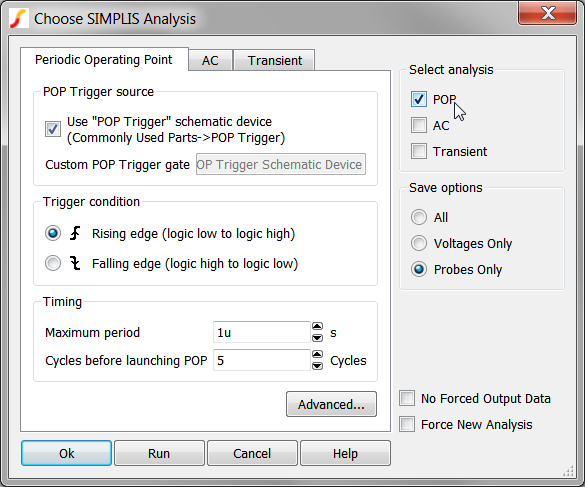
- Press F8 to open the Choose SIMPLIS Analysis dialog.Result: The Choose SIMPLIS Analysis dialog opens:
- Click on the Run button to run the simulation. Result: The simulation halts with a syntax error. The following message box opens:

This error message communicates the steps required to remedy this error, that is, to add a POP Trigger schematic device to the design. In the next exercise, you will follow the error message instructions and add a POP Trigger schematic device.
Run-time Errors
Often a POP simulation will run, but errors are generated for one of these two reasons:
- The POP Trigger schematic device is incorrectly connected to the circuit, or
- The analysis parameters are incorrect.
Exercise #2: Add POP Trigger w/ Incorrect Maximum POP Period Specified
In this exercise you will add the POP Trigger schematic device, and run the simulation.
- Open the parts selector using the menu item.
- Select the Commonly Used Parts category
- Select the POP Trigger device.
- Click on the Place POP Trigger hyperlink.
- Move the mouse over to the wire connected to the SW node.
- Click the mouse to place the POP Trigger device. Result: your schematic should appear as follows:
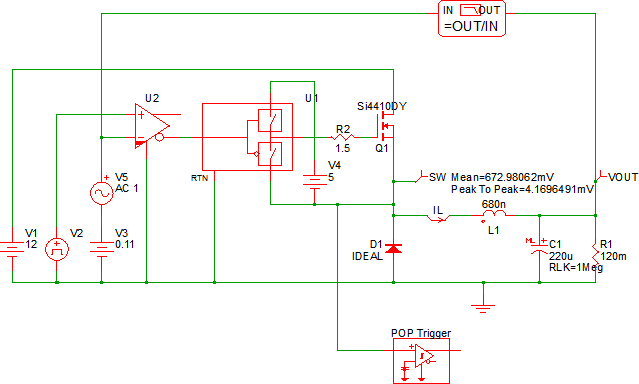
- Run the simulation. Result:
- The POP simulation fails to converge because the maximum POP period is set to 1us, while the converter has a 2us period.
- A transient simulation is launched for 100us, which is 100 times the maximum POP period parameter.
- A error message is output to the SIMetrix/SIMPLIS command shell.
The error message which is generated is:
****************************************
<<<<<<<< Error Message ID: 5020 >>>>>>>>

Periodic Operating-Pt Analysis:
     Reaching a time duration equal to
     `2.00000e-006' without registering the
     triggering condition that defines
     the start of a period.  Check your
     circuit and/or initial conditions.
The error message in this exercise also occurs whenever the circuit stops switching for a time period greater than the Maximum period parameter. In this case, the circuit never switches at a period less than the Maximum period parameter.
In the next exercise you will set the Maximum POP Period and successfully run the POP analysis.
Exercise #3: Specify Appropriate Maximum POP Period
Using the same schematic as you used in the previous example,
- Press F8 to open the Choose SIMPLIS Analysis dialog.
- Change the Maximum period parameter to 2.1us. The configured dialog will
appear as follows:

- Run the simulation. Result: The POP simulation converges and 5 cycles of the POP waveforms are output to the waveform viewer:

Conclusions and Key Points to Remember
- There are a number of POP syntax errors which cause a circuit which would otherwise successfully converge in a POP analysis to abort before the simulation starts.
- SIMPLIS needs to know the maximum period for your circuit. Therefore an incorrect Maximum period parameter will cause POP to fail.
- The program audits the schematic for POP Trigger schematic devices. Only one device is allowed in a design, and the output of that device is used for the POP trigger TRIG_GATE parameter.