To download the examples for Module 2, click Module_2_Examples.zip
In this topic:
What You Will Learn
- How to add curves to the waveform viewer once the simulation completes by probing the schematic.
- The advanced probes are on the More Probe Functions... menu.
Getting Started
Exercise #1: Random Probe a Voltage
- Open the schematic 2.4_SelfOscillatingConverter_POP_Tran.sxsch.
- Run the simulation.
- From the schematic menu, select Probe ▶
Current in Device Pin...
Result: The mouse cursor symbol changes to a probe symbol:

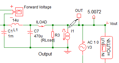
- Move the mouse to the upper pin of the load current generator I1 at the
converter output:

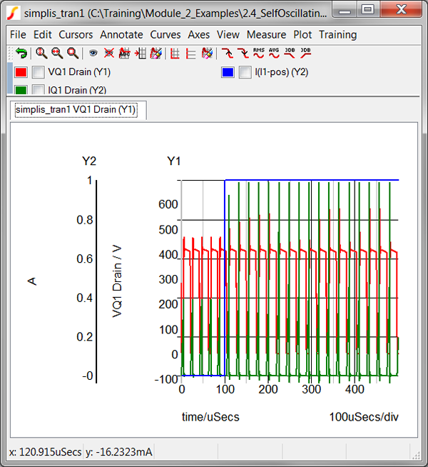
- Click the left mouse button. Result: The pin current of the load current generator I1 is plotted on a new graph axis. Note: A positive pin current is defined as a current flowing into the pin.

Discussion
In the previous topic, 2.3 Managing Simulation Data, you learned how to output voltage and current vectors to the data group. Once these vectors are present in the current data group, you can plot them on the waveform viewer. In SIMetrix/SIMPLIS, this action is called random probing, and is commonly used to debug circuits. In this section you will learn how to use some very powerful random probing functions.
More Probe Functions Menu
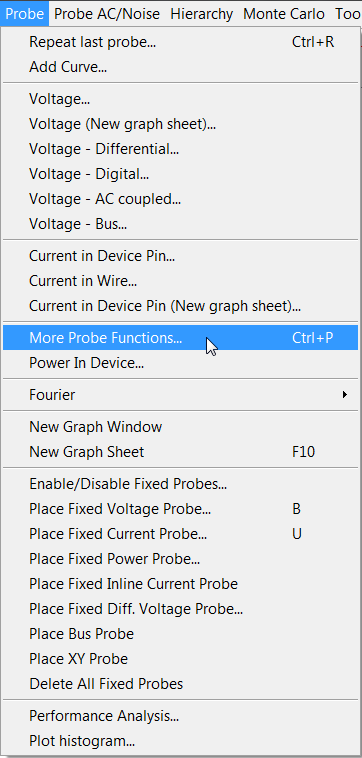
In section 2.3 Managing Simulation Data, you used random probing to plot a voltage. In the Getting Started section of this topic, you randomly probed a pin current. The most often used random probe functions are listed on the schematic menus Probe, and Probe AC/Noise. The advanced probe functions are located on the schematic menu Probe ▶ More Probe Functions... menu:

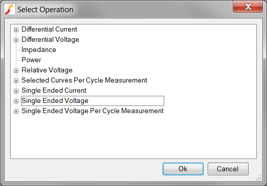
Selecting the More Probe Functions... menu item opens a tree selection dialog containing the advanced probing features. For convenience, the training scripts define the shortcut key Ctrl+P to execute this menu item. The tree selection dialog which opens is shown below.

In the next topic, 2.4.2 Generating Per Cycle Curves, you will use the per cycle probes to measure and plot converter behavior on a cycle-by-cycle basis.
Conclusions and Key Points to Remember
- Some of the most powerful graphing capabilities within SIMetrix/SIMPLIS are located on the More Probe Functions... menu.
- The most commonly used random probe functions are located on the schematic Probe menu.