This section of the tutorial deals with user-defined models. You will continue with the schematic that you saved in 2.4 Edit Parameter-Extracted Models and then change the diode to a user-defined model.
In this topic:
Key Concepts
This topic addresses the following key concepts:
- A user-defined diode model can be used to model an ideal synchronous rectifier, with the minimum of circuit components.
- Diode models are implemented with PWL resistors in SIMPLIS.
What You Will Learn
In this topic, you will learn the following:
- How to model a synchronous rectifier with a user-defined diode.
2.5.1 Model a Synchronous Rectifier with a User-defined Diode
SIMPLIS Diode models are PWL resistors with a high off-resistance and a low on-resistance. The parameter-extracted models use a three segment model, where the third segment represents an intermediate resistance between the high off-resistance segment and the low on-resistance segment.
The user-defined model uses a two segment model and you can enter the resistance and voltage values into the dialog. Although it might not be obvious at first, this model can represent an ideal synchronous rectifier with the following characteristics:
- The forward voltage of the diode is 0V.
- When the diode current is positive, the diode has a forward resistance equal to the on-resistance of the synchronous rectifier MOSFET.
- When the diode current is negative, the diode turns off and the resistance is high, representing the off-resistance of the synchronous rectifier MOSFET.
- Because the diode turns on and off in response to the circuit voltages and currents, the timing for the synchronous rectifier is ideal, that is, no dead time or drive signal is required.
You will now change the diode to use the user-defined model and enter the parameters to make it behave like an ideal synchronous rectifier MOSFET.
To change the diode to a user-defined model, follow these steps:
- Double click the D1 symbol. Result: The Extract Diode : D1 Parameters dialog opens.
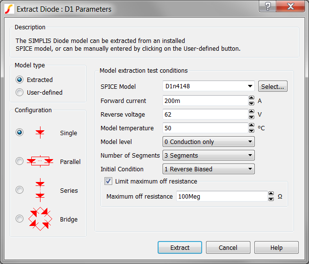
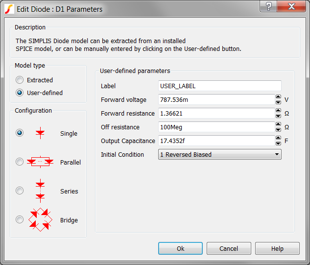
- Click the User-defined radio button on the upper left side of the dialog.Result: The parameters on the right side of the dialog change to User-defined parameters.Note: The User-defined parameters are set to the values calculated in the last parameter extraction.
- Make the following changes to the User-defined parameters:
Parameter label Value Label ideal_sr Forward voltage 0 Forward resistance 10m Output Capacitance 0 Result: The dialog should now look like this: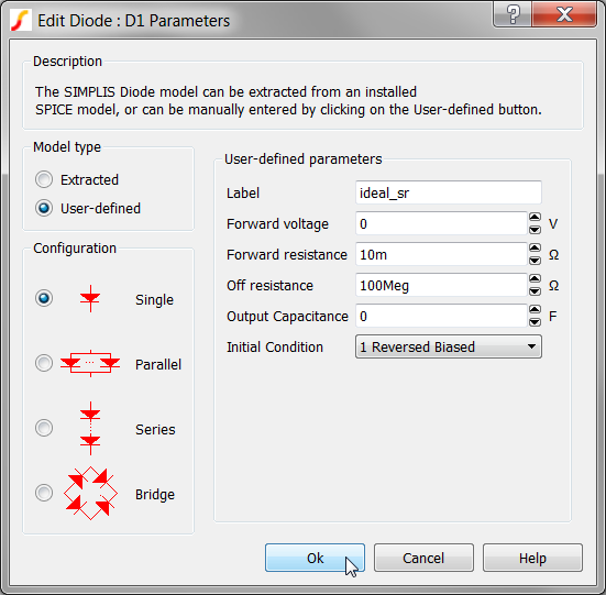
- Click OK.Result: The diode now represents an ideal synchronous rectifier with a 10mΩ on-resistance and 100MegΩ off-resistance. The forward voltage drop is 0V.
2.5.2 Save your Schematic
To save your schematic, follow these steps:
- Select .
- Navigate to your working directory where you are saving your schematics.
- Save the file as 2_my_buck_converter.sxsch.
- When prompted to overwrite the existing file, click Yes.
A schematic saved at this state can be downloaded here: 2_SIMPLIS_tutorial_buck_converter.sxsch.