DVM - Design Verification Module
DVM - Design Verification Module
|
The purpose of the AcSteadyState() test is to measure the steady-state
behavior of the supply, including the conducted line spectrum, efficiency,
and the power factor. The input is configured as an AC
Fixed Input Source, and the output is configured as a Resistive
Load. The initial conditions for the simulation are typically found
with a FindAcSteadyState(), test
which runs a long transient simulation and saves the initial conditions
using the GenerateInitFile testplan
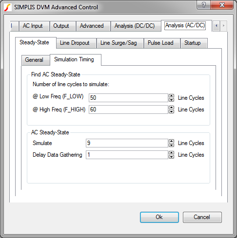
entry. The AcSteadyState() test runs a transient simulation on the converter
with timing based on values entered in the Steady-State/Simulation
Timing tab, which is shown below and accessed from the Full Power Assist DVM control symbol.
This test objective measures the following scalar values:
In this Topic Hide
The AcSteadyState() function has the following syntax with the arguments described in the table below:
AcSteadyState(REF, LINE_RANGE, VOLTAGE, FREQUENCY)
AcSteadyState(REF, LINE_RANGE, VOLTAGE,
FREQUENCY, OPTIONAL_PARAMETER_STRING)
| Argument | Range | Description |
REF |
n/a |
The actual reference designator of the DVM Source or the generic syntax of INPUT:n where n is an integer indicating a position in the list of managed DVM sources. |
LINE_RANGE |
LL or HL |
The line range to select the correct symbolic voltage value. This can only be the two strings LL or HL. |
VOLTAGE |
min:0 |
The RMS voltage for the input source. The voltage can be a numeric value or a symbolic value, such as a percentage of nominal input voltage. Symbolic values use the LINE_RANGE parameter to find the correct symbolic value. |
FREQUENCY |
min: > 0 |
The AC line frequency of the input source. This is used to both set the frequency of the input source and to set the simulation timing. The frequency can be a numeric or a symbolic value, such as F_High or F_Low. |
OPTIONAL_PARAMETER_STRING |
n/a |
Parameter string with a combination of one or more timing parameters:
|
* If more than one parameter is specified, join the parameter key-value pairs with a space, as shown in the example below. The order of the parameter names does not matter.
DVM sets the timing parameters for the AcSteadyState() test objective based on values that you enter on the Steady-State/Simulation Timing tab of the Full Power Assist DVM control symbol. The two simulation times are:
\[ \text{STOP_TIME} = \frac{\text{Simulate}}{\text{FREQUENCY}}\]
\[ \text{DATA_START_TIME} = \frac{\text{Delay Data Gathering}}{\text{FREQUENCY}}\]
The AcSteadyState() test objective sets the source and load subcircuits to the following:
| Source | Control Source (if used) | Load |
Loads other than the output under test are set to the Resistive Load. All other sources are set to either the DC Input Source for DC sources or the AC Fixed Input Source for the AC input sources.
The AcSteadyState() test objective measures the following scalar values where {load_name} is the name assigned to each load, and {source_name} is the name assigned to each source.
Scalar Name |
Description |
Efficiency |
The overall efficiency of the converter. Only managed sources and loads are included in this calculation. Independent sources or DVM Aux. sources are not included. |
Frequency({source_name}) |
A number which represents the line frequency. |
Power({source_name}) |
The power for the input source. |
Power({load_name}) |
The power for the output load. |
Power_Factor({source_name}) |
The power factor for the input source. |
THD({source_name}) |
The total harmonic distortion for the input source. |
V{load_name}%_diff_last_2_linecycles |
The percent change in the output voltage when averaged over the last two line cycles. |
| EvenHarmonic(I{source_name}) | A table of the 20 even source current harmonics. These are output only if you select the Both or Even options in the Calculate entry on the DVM Control Symbol GUI. See AC/DC Harmonic Specifications for more information. |
| OddHarmonic(I{source_name}) | A table of the 20 odd source current harmonics. These are output only if you select the Both or Odd options in the Calculate entry on the DVM Control Symbol GUI. See AC/DC Harmonic Specifications for more information. |
V{load_name} Last LineCycle |
The average value of the output voltage during the last line cycle in the simulation. Used for the V{load_name}%_diff_last_2_linecycles calculation. |
V{load_name} Previous LineCycle |
The average value of the output voltage during the second to the last line cycle in the simulation. Used for the V{load_name}%_diff_last_2_linecycles calculation. |
| I{load_name} | Minimum and Maximum values of the load current. |
| V{load_name} | Minimum and Maximum values of the load voltage. |
| I{source_name} | Average, Minimum, Maximum, and RMS values of the source current. |
| V{source_name} | Minimum, Maximum, and RMS values of the source voltage. |
| I{load_name} in Reg. | Average, Minimum, Maximum, and RMS values of the load current when the converter is in regulation. |
| V{load_name} in Reg. | Average, Minimum, Maximum, and RMS values of the load voltage when the converter is in regulation. |
In the following table, {load_name} is the name assigned to each load. The default value is LOAD. DVM forces each load name to be unique so that the scalar and specification values for each load are unique.
Specification Name |
PASS/FAIL Criteria |
AC_Settling({load_name}) |
The percentage change in the output load voltage over the final two line frequency cycles is less than the maximum specification value. |
Min_V{load_name} |
The minimum value of the output during the simulation time is greater than the minimum specification value. |
Max_V{load_name} |
The maximum value of the output during the simulation time is less than the maximum specification value. |
Min_V{load_name}_reg |
The minimum value of the output at the end of the simulation time is greater than the minimum specification value. |
Power_Factor({source_name}) |
The power factor of the input source is greater than the limit. |
Max_V{load_name}_reg |
The maximum value of the output at the end of the simulation time is less than the maximum specification value. |
Class A|B|C|D Harmonic Limits |
Each harmonic scalar value is checked against the specification value. If all harmonics pass, this specification will be a PASS. If any harmonic scalar value is greater than the specification value, the test status is set to FAIL. Failing harmonics will be individually logged. |
User-Specified Harmonic Limits |
User defined harmonic limits are handled as the Class A|B|C|D limit above. For details on setting user defined harmonic limits, see the AC/DC Harmonic Specifications topic. |
The AcSteadyState() test objective is used in the built-in AC/DC testplans. Shown below is a single AcSteadyState() test from the AC/DC (1-input/1-output) testplan. This test configures the load to the 100% load symbolic value, and the input source to the HL Maximum symbolic value, and the line frequency to the F_Low symbolic value. The output load symbolic values are defined on the Output tab, and the AC source symbolic parameters are defined on the AC Input tab of the Full Power Assist DVM control symbol.
| *?@ Analysis | Objective | Source | Load | Label | GenerateInitFile | IncludeInitFile |
| Transient | AcSteadyState(INPUT:1, HL, Maximum, F_Low) | LOAD(OUTPUT:1,100%) | Transient|AcSteadyState|HL_Maximum|F_Low|100% Load | INITFILE_HL_Maximum_F_Low_100% Load |
The following AcSteadyState() test objective uses the OPTIONAL_PARAMETER_STRING argument to set the simulation stop time to 220ms (11 cycles@50Hz) and to delay data gathering for a single line cycle. The resulting data will have 10 complete line cycles of simulation data.
AcSteadyState(INPUT:1, HL, Maximum, F_Low, NCYCLES_STOP=11 NCYCLES_DELAY=1)
You can view the complete test report in a new browser window here: AcSteadyState() Test Report. Below is an interactive link to the same test report.
© 2015 simplistechnologies.com | All Rights Reserved